Create a Gear Assembly Using Siemens NX 12: This comprehensive guide will walk you through the process of designing and assembling gear components using the powerful Siemens NX 12 software. We’ll explore the fundamental concepts of gear design, including different gear types, ratios, and tooth profiles. From initial setup to advanced techniques, this guide will provide a detailed roadmap to creating professional-quality gear assemblies in NX 12.
We’ll delve into the software’s capabilities, demonstrating how to model individual gear components, assemble them into a complete system, and optimize the design for efficiency. Learn about constraints, mates, and interference checks, crucial for creating accurate and functional gear assemblies. Finally, we’ll cover generating detailed drawings and documentation using NX 12’s robust features.
Introduction to Gear Assemblies in Siemens NX 12
Gear assemblies are fundamental components in numerous mechanical systems, from automobiles and industrial machinery to consumer electronics. They transmit power and motion between rotating shafts, enabling diverse functionalities. Proper design and accurate modeling of gear assemblies are crucial for ensuring smooth operation, efficiency, and longevity.The precision of gear design hinges on understanding gear types, ratios, and tooth profiles.
A well-designed gear assembly considers factors like load capacity, speed requirements, and the specific application. Siemens NX 12 provides a powerful platform for creating and managing these complex assemblies, streamlining the design process and enhancing the accuracy of the final product.
Gear Types and Their Characteristics
Gears are categorized into various types, each with unique properties and applications. Understanding these types is vital for selecting the appropriate gear for a given design.
Learning how to create a gear assembly using Siemens NX 12 is a fascinating process. It’s like building something complex from scratch, a mechanical marvel. Thinking about the intricate workings of such a system, I find myself pondering the broader concept of existence and the mysteries of life after death, particularly the ideas explored in the “death after life iv” series.
death after life iv delves into some truly profound questions. Ultimately, though, my focus returns to the task at hand, and I’m eager to continue mastering the techniques of creating a gear assembly using Siemens NX 12.
- Spur Gears: These are the most common type of gear, characterized by teeth parallel to the axis of rotation. Their straightforward design makes them suitable for applications requiring high power transmission at moderate speeds. Spur gears are generally used in applications where the shafts are aligned.
- Helical Gears: Helical gears have teeth that are inclined to the axis of rotation. This design provides smoother power transmission compared to spur gears and reduces noise at higher speeds. Helical gears are often preferred for applications where the shafts are aligned but need to transmit power at higher speeds or where noise reduction is critical.
- Bevel Gears: Bevel gears are used to transmit power between shafts that intersect at an angle. They come in various forms, including straight bevel gears, spiral bevel gears, and hypoid gears. The choice of bevel gear type depends on the angle between the shafts and the required load capacity.
- Worm Gears: Worm gears are characterized by a worm and a worm wheel. The worm is a single-threaded screw, while the worm wheel has teeth that mesh with the worm. They provide a high gear ratio with a relatively compact design. Worm gears are frequently employed in applications requiring high reduction ratios, such as in clocks and positioning systems.
Gear Ratios and Their Significance
Gear ratios determine the speed and torque relationship between input and output shafts in a gear assembly.
A gear ratio is the ratio of the number of teeth on the driven gear to the number of teeth on the driving gear.
A higher gear ratio results in a lower output speed and higher output torque, and vice versa. This relationship is critical in various applications, allowing designers to control the speed and torque characteristics of the output shaft based on the input shaft’s specifications.
Tooth Profiles and Their Impact on Performance
The shape and profile of gear teeth significantly impact the performance of a gear assembly.
- Involute Profiles: Involute profiles are the most common tooth profiles used in gear design. They offer smooth transmission and are well-suited for various applications. The involute profile’s unique properties enable precise meshing and reduce noise and vibration.
- Cycloidal Profiles: Cycloidal profiles, while less common, offer certain advantages in specific applications. They may be preferred for situations where very high accuracy and load capacity are paramount. They are sometimes used in high-precision machinery.
Siemens NX 12 for Gear Assembly Creation
Siemens NX 12 provides robust tools for modeling, analyzing, and managing gear assemblies. The software facilitates the creation of complex gear systems, incorporating different gear types and profiles.
- Creating Geometry: NX 12 allows for the creation of individual gear components using parametric modeling techniques. This ensures that the gear geometry accurately reflects the design specifications.
- Assembly Management: NX 12 enables the seamless assembly of individual gear components into a complete gear train. The software supports constraints and relationships to ensure proper alignment and meshing of gears.
- Analysis and Simulation: NX 12 offers tools for analyzing the stress, strain, and performance of the gear assembly. This enables designers to identify potential issues and optimize the design for optimal performance.
Modeling Gear Components
Creating gear components in Siemens NX 12 involves a meticulous process, starting with accurate sketching and progressing through 3D modeling. A fundamental understanding of gear types and their specific characteristics is crucial for generating precise models. This detailed approach ensures the final gear assembly is not only functional but also meets the required specifications.Careful attention to dimensions and tolerances is paramount in gear design.
Inaccurate specifications can lead to malfunctioning mechanisms and decreased performance. By following a structured approach, designers can ensure the precision required for optimal gear functionality.
Sketching Gear Profiles
A well-defined sketch is the foundation for any gear component. Sketching provides a visual representation of the gear’s profile and establishes the basic geometry. Different sketching tools in NX 12, such as lines, circles, and arcs, allow for the creation of intricate gear profiles. The precision of the sketch directly influences the accuracy of the final 3D model.
Creating Gear Types in NX 12
NX 12 offers dedicated tools for creating various gear types. These tools streamline the process, eliminating the need for complex manual calculations. Using these tools, users can create spur gears, helical gears, bevel gears, and more, each with specific tooth profiles and geometric characteristics.
Creating Spur Gears
Spur gears are the simplest type. Their teeth are parallel to the axis of rotation. NX 12’s dedicated gear creation tools allow for easy specification of parameters like module, pressure angle, and number of teeth. The process typically involves defining the module, the number of teeth, and the pressure angle. These parameters dictate the gear’s dimensions and operating characteristics.
Creating Helical Gears
Helical gears feature teeth that are inclined to the axis of rotation. This design provides smoother transmission and reduces noise compared to spur gears. In NX 12, users can specify the helix angle to define the inclination of the teeth. Accurate definition of the helix angle is essential for correct gear operation.
Creating Bevel Gears
Bevel gears transmit power between shafts that intersect. NX 12’s tools allow for the creation of these gears with precise angles and tooth profiles. Defining the intersection angle and the number of teeth on each gear is critical for a functional assembly.
Creating Worm Gears
Worm gears use a worm screw and a worm wheel to transmit motion. NX 12’s features support the creation of worm gears, allowing for specification of the worm’s thread angle and the wheel’s number of teeth. The precise definition of these parameters is essential for correct gear performance.
Importance of Dimensions and Tolerances
Accurate dimensions and tolerances are crucial for ensuring proper meshing and functionality. The specified tolerances will dictate how much variation is permitted in the gear’s dimensions.
“Gear tooth profiles must be precise to avoid interference and ensure smooth operation.”
Deviation from the specified tolerances can lead to issues in the gear assembly.
Creating Gear Teeth Using NX 12 Tools
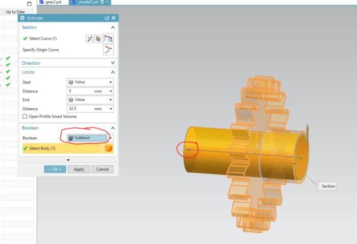
NX 12 offers dedicated tools to generate gear teeth. A typical procedure involves defining the gear parameters, generating the base profile, and using a gear tool to extrude the teeth. The parameters for tooth height, width, and profile are carefully set to match the design requirements. The use of the dedicated tools is recommended to ensure consistency and avoid errors.
Creating a gear assembly in Siemens NX 12 is a fascinating process, and it’s great to see the precision involved. It’s almost like a mini-factory in your software, isn’t it? Speaking of precision and intricate design, have you heard about the new compilation of Joy Division and New Order? Their combined best of, joy division and new order get joint best of , is a must-listen for any music fan.
Back to the gear assembly, it’s a rewarding project to complete and perfect the design.
Assembling Gear Components: Create A Gear Assembly Using Siemens NX 12
Putting together gear assemblies in Siemens NX 12 involves careful planning and execution. The process is crucial for ensuring the mechanical integrity and functionality of the final product. Understanding the specific methods for connecting gears and the appropriate use of constraints is paramount for a successful assembly. This section details the procedures for achieving a robust and accurate gear assembly.
Attaching Gears to Shafts
A critical aspect of gear assembly is connecting gears to their respective shafts. This typically involves creating a cylindrical hole in the gear that aligns precisely with the shaft’s diameter. The shaft is then inserted into the gear, ensuring a secure fit. NX 12 provides tools to accurately define the shaft diameter and the gear’s bore. This ensures proper concentricity and minimizes potential misalignment issues.
Careful attention to tolerances is vital.
Utilizing Constraints and Mates
Constraints and mates are essential for controlling the relative positions of components in the assembly. They prevent unwanted movement and ensure that the gears rotate correctly. Applying appropriate constraints, like coincident, parallel, and perpendicular mates, fixes the position and orientation of gears and shafts within the assembly.
Creating and Modifying Assembly Configurations
NX 12 allows for the creation of multiple assembly configurations. This is helpful for analyzing different scenarios or states of the assembly. For example, one configuration might represent the assembly in its initial state, while another might represent a specific operating condition. Modifying configurations involves changing the constraints or positions of components to reflect the desired state.
Creating a well-structured hierarchy of configurations is important for efficient management and manipulation of assembly states.
Types of Constraints in Gear Assemblies
Understanding the various types of constraints is crucial for achieving a well-defined and functional gear assembly. The following table Artikels common constraints and their application in gear assemblies.
| Constraint Type | Description | Application in Gear Assemblies |
|---|---|---|
| Mate | A mate constraint defines a relationship between two components, specifying how they are connected. | Used to define the connection between a gear and its shaft. |
| Coincident | This constraint ensures that two points or faces are placed at the same location. | Ensuring that a gear tooth aligns with a shaft. |
| Parallel | This constraint ensures that two edges or faces are parallel to each other. | Ensuring gears are aligned correctly for proper meshing. |
| Perpendicular | This constraint ensures that two edges or faces are perpendicular to each other. | Establishing the correct angular relationship between gears. |
Modifying and Optimizing Gear Assemblies
")
Fine-tuning gear assemblies in Siemens NX 12 is crucial for achieving optimal performance and functionality. This process involves modifying existing components, adjusting parameters, and rigorously verifying the design. Proper modification techniques ensure the final assembly meets the required specifications and avoids potential issues like interference or stress concentrations.Efficient modification of gear assemblies involves understanding the relationships between components and the implications of changes on the overall system.
This allows for iterative improvements and ensures the final design aligns with desired characteristics and constraints. Knowing how to add, remove, and modify components and parameters, along with performing comprehensive checks, is key to successful gear assembly optimization.
Modifying Existing Gear Assemblies in NX 12
Modifying existing gear assemblies involves various techniques in NX 12, enabling designers to refine the assembly without starting from scratch. Direct manipulation of components, parametric changes to geometry, and alterations to assembly constraints are some common methods. This often involves a detailed understanding of the component relationships within the assembly.
Adding or Removing Components from an Assembly
Adding or removing components from an existing assembly requires careful consideration of the assembly structure and its impact on other components. NX 12’s powerful features facilitate this process. Carefully examining the assembly’s constraints and relationships is essential. This avoids unintended consequences and ensures the integrity of the remaining components. Improper modification can lead to interference issues or stress concentrations.
Modifying Gear Parameters
Modifying gear parameters, such as module, pressure angle, and tooth profiles, is often required for optimization. These parameters directly affect the gear’s performance characteristics, such as load capacity and efficiency. The assembly environment in NX 12 allows for parametric modifications, which update all related components automatically. This ensures consistency and reduces errors.
Performing Interference Checks
Performing interference checks is critical to avoid design issues. This involves verifying that components do not collide or interfere with each other after modifications. Using NX 12’s interference checking tools can identify potential problems. This proactive step helps catch errors early in the design process, preventing costly rework or failures during manufacturing.
Example: Modifying Gear Meshing Parameters
Consider a gear assembly where the gear meshing needs adjustment. The module of the gear needs to be increased to reduce the gear’s load. Using NX 12’s parametric features, the module value for the gear can be modified. This update will automatically adjust the gear geometry, ensuring consistency across the assembly. Subsequently, interference checks are crucial to verify that the modification hasn’t introduced any interference issues.
Analyzing the modified assembly’s stresses and load distribution is essential to ensure the gear can handle the increased load. Using the simulation tools in NX 12, designers can simulate the assembly under various conditions and analyze the effects of the modification on the overall system.
Generating Drawings and Documentation
Documenting your gear assembly is crucial for communication, manufacturing, and future reference. Accurate drawings and a comprehensive Bill of Materials (BOM) ensure everyone involved understands the design and facilitates the production process smoothly. This section details the procedures for generating these essential documents within Siemens NX 12.
Generating 2D Drawings in NX 12
The process involves creating both detailed part and assembly drawings. Part drawings focus on individual components, while assembly drawings showcase the complete gear assembly. Both are vital for manufacturing and design review.
Creating Detailed Part Drawings
To generate a part drawing, select the relevant part in the model tree. Open the “Drawings” tab and choose “Create Drawing.” NX 12 offers templates for various drawing types, allowing you to quickly configure the drawing layout. Specify the desired views (e.g., front, top, side), and NX 12 automatically generates the corresponding projections. You can customize these views by adding dimensions, tolerances, and annotations.
Diving into creating a gear assembly using Siemens NX 12 is always a fascinating project. It’s a rewarding challenge, pushing my CAD skills to the next level. While I’m immersed in the intricate details of gear tooth profiles and tolerances, it’s nice to take a break and check out Sufjan Stevens’ upcoming live performance of a film score, sufjan to perform live film score.
Back to the drawing board, I’m eager to continue refining my gear assembly design in NX 12.
Ensure accurate representation of features, material specifications, and any critical dimensions. Adding notes and specifications helps avoid ambiguity.
Creating Assembly Drawings
Assembly drawings provide a comprehensive view of the complete gear assembly. Select the assembly in the model tree, then proceed to create a drawing. The process is similar to creating part drawings, but the assembly drawing showcases the components in their assembled state. Use appropriate view types (e.g., exploded view, isometric view) to clearly depict the interrelationships between the components.
Dimensioning and annotation are critical for clarity and accurate reproduction.
Generating Section Views
Section views reveal internal details of the assembly. By selecting a section plane, you can generate a cross-sectional view, exposing the internal geometry of the gear teeth and other relevant features. This technique is particularly useful for visualizing complex geometries and confirming design intent. Ensure that the section plane cuts through the critical features for proper representation.
Generating Bill of Materials (BOM) in NX 12
The Bill of Materials (BOM) lists all the components and their quantities required for the gear assembly. NX 12 automatically generates a BOM based on the assembly model. You can access it from the assembly model tree, or via the drawing itself. This feature is crucial for production planning and inventory management.
Steps for Generating Different Drawings and Reports, Create a Gear Assembly Using Siemens NX 12
| Drawing Type | Description | Purpose |
|---|---|---|
| Part Drawing | Detailed view of a single component. | Provides detailed information for manufacturing and design review of each part. |
| Assembly Drawing | Complete view of the assembled gear components. | Illustrates the complete assembly, showing interrelationships between components. |
| Section View | Cross-sectional view of the assembly. | Reveals internal features and geometries for design analysis and manufacturing. |
Advanced Gear Assembly Techniques
Beyond the basics of modeling and assembling gears in NX 12, advanced techniques unlock greater design control and optimization. These methods, incorporating parametric modeling and simulation, empower engineers to create more robust and efficient gear assemblies, capable of handling complex loads and conditions.
Parametric Modeling for Gear Design
Parametric modeling in NX 12 provides a powerful approach to gear design. By defining parameters for gear dimensions (module, pressure angle, tooth count), the design becomes adaptable to variations. Changes in one parameter automatically update the entire model, streamlining the design process and enabling iterative improvements.
Gear Meshing and Contact Simulation
Simulating gear meshing and contact is crucial for predicting performance and identifying potential issues. NX 12 offers tools to model the contact between gear teeth, enabling engineers to analyze stress distributions, contact pressures, and potential wear. This allows for early detection of potential failures and enables design adjustments before physical prototyping.
Detailed Analysis Reports
NX 12 provides comprehensive analysis reports that visualize the results of simulations and calculations. These reports can detail stress concentrations, contact pressures, and power transmission characteristics, allowing engineers to thoroughly assess the performance of the gear assembly. This data is essential for informed design decisions and ensures that the assembly meets specified performance criteria.
Gear Assembly Optimization
Optimizing gear assemblies for performance and efficiency is a crucial aspect of advanced design. This involves selecting optimal gear ratios, material choices, and manufacturing processes. NX 12 allows for iterative design adjustments based on simulation results, enabling the assembly to meet performance targets while minimizing weight and cost.
Complex Gear Assembly Examples
Several complex scenarios illustrate the application of advanced techniques. Examples include:
- Planetary Gear Trains: Modeling planetary gear trains involves intricate tooth meshing and complex load distributions. Simulation helps predict dynamic behavior and ensure smooth operation.
- Helical Gears with Staggered Teeth: Creating helical gears with staggered teeth requires careful modeling and simulation to account for the unique contact patterns and load paths. This improves efficiency and reduces noise.
- Gear Assemblies with Multiple Inputs and Outputs: Designing gear assemblies with multiple inputs and outputs requires careful consideration of the gear ratios and power transmission paths. Simulations help engineers optimize the overall system performance.
- Gear Assemblies with Variable Loads: Gear assemblies operating under varying load conditions necessitate detailed analysis to determine the stress and strain distributions. Simulation helps determine the assembly’s robustness under dynamic loads.
Advanced Features for Gear Design
NX 12 incorporates several features that aid in advanced gear design. These include advanced surfacing techniques, powerful constraint tools, and extensive simulation capabilities. Using these features allows for the creation of precise and optimized gear assemblies.
Last Point
")
In conclusion, this guide has provided a detailed walkthrough of creating gear assemblies in Siemens NX 12. By understanding the fundamental concepts and practical steps, you can confidently design and assemble complex gear systems. The detailed examples and practical exercises will empower you to effectively utilize NX 12’s capabilities to develop professional-quality gear assemblies. Remember, mastering the software takes practice, so continue exploring the software’s functionalities to enhance your gear design expertise.