Calculate Total Resistance in Circuits is crucial for understanding and designing electrical systems. This comprehensive guide delves into the principles of resistance in various circuit configurations, from simple series and parallel arrangements to more complex mixed circuits. We’ll explore the fundamental concepts, formulas, and practical applications, providing you with the knowledge to confidently analyze and solve electrical problems.
This in-depth exploration covers the factors influencing resistance, Ohm’s Law, and the distinct behaviors of resistors in series, parallel, and mixed circuits. We’ll use clear examples and tables to illustrate the concepts and guide you through practical problem-solving techniques.
Introduction to Circuit Resistance
Electrical resistance is a fundamental property of materials that opposes the flow of electric current. Understanding resistance is crucial for analyzing and designing electrical circuits, as it dictates how much current will flow under a given voltage. Resistance is measured in ohms (Ω).Resistance is not a mysterious force but a consequence of the interactions between electrons and the material’s atomic structure.
Calculating total resistance in circuits can be tricky, but it’s a fundamental concept. It’s like figuring out how many lanes a highway has to determine traffic flow. Sometimes, it’s all about how Kid Cudi feels about his Yeezus feature, a subject of some discussion recently, as evidenced by this article. Ultimately, understanding these concepts helps us build better circuits, just like planning a smooth commute.
So next time you’re working on a circuit, remember the basics of total resistance.
The movement of electrons through a material is hindered by collisions with atoms within the material, and this hindrance is what we perceive as resistance.
Factors Influencing Resistance
Various factors affect the resistance of a material. The intrinsic nature of the material itself plays a significant role, as some materials offer more opposition to current flow than others. The length of the material also affects resistance; longer materials generally exhibit higher resistance. A wider cross-sectional area, conversely, leads to lower resistance, as there’s more space for electrons to flow.
Temperature also impacts resistance, often increasing with rising temperature in conductors.
Relationship Between Voltage, Current, and Resistance (Ohm’s Law)
Ohm’s Law establishes a fundamental relationship between voltage (V), current (I), and resistance (R) in an electrical circuit. This relationship states that the current flowing through a conductor is directly proportional to the voltage across it and inversely proportional to its resistance. Mathematically, this is expressed as:
V = I
R
where V is the voltage in volts, I is the current in amperes, and R is the resistance in ohms.
Table: Voltage, Current, and Resistance in a Single Resistor Circuit
| Voltage (V) | Current (I) | Resistance (R) |
|---|---|---|
| 10 V | 2 A | 5 Ω |
| 5 V | 1 A | 5 Ω |
| 20 V | 4 A | 5 Ω |
This table demonstrates how the current changes with different voltages while the resistance remains constant.
Common Electrical Circuit Components
A variety of components make up electrical circuits. Understanding their individual roles is essential to comprehending circuit function.
- Resistors: Resistors impede the flow of current in a circuit, controlling the amount of current. They are used to limit current flow, divide voltage, and create specific circuit functions. A simple example is a light bulb filament, which acts as a resistor to limit the current flow and produce light.
- Capacitors: Capacitors store electrical energy in an electric field. They are used in circuits to smooth out voltage fluctuations, block DC current while allowing AC current to pass, and filter out unwanted frequencies.
- Inductors: Inductors store energy in a magnetic field. They are used in circuits to resist changes in current, filter out high-frequency signals, and create tuned circuits for radio transmission and reception.
- Diodes: Diodes allow current to flow in one direction but not the other. They are used to rectify alternating current (AC) to direct current (DC), protect circuits from reverse voltage, and create voltage regulation circuits.
- Transistors: Transistors are semiconductor devices that can act as switches or amplifiers. They are the fundamental building blocks of modern electronic circuits, enabling a wide range of functionalities from digital logic to power amplification.
- Switches: Switches control the flow of current in a circuit. They are used to turn circuits on and off, and can be used to create more complex circuit control mechanisms.
- Wires: Wires connect components in a circuit. While often overlooked, the resistance of the wires can be significant in certain applications, especially at higher currents.
Calculating Resistance in Series Circuits

Resistors connected in series share the same current flowing through them. This unique characteristic allows us to calculate the total resistance of the circuit in a straightforward manner. Understanding how resistances combine in series is crucial for designing and analyzing various electronic circuits.The total resistance in a series circuit is the sum of the individual resistances. This principle stems from the fact that the current must pass through each resistor sequentially.
Each resistor opposes the current flow, and the overall opposition is the sum of these individual oppositions. This predictable behavior makes series circuits easy to analyze and design.
Calculating Total Resistance
The formula for calculating the total resistance (R T) in a series circuit is remarkably simple. It’s the sum of all the individual resistances (R 1, R 2, R 3, etc.) in the circuit.
RT = R 1 + R 2 + R 3 + …
This straightforward addition directly reflects the cumulative effect of each resistor on the current flow. The more resistors there are, the higher the total resistance.
Why Resistances Add Up in Series, Calculate Total Resistance in Circuits
The cumulative effect of resistances in series is a direct consequence of the current path. Current flows through each resistor consecutively. Each resistor introduces an additional opposition to the flow of current. The total resistance is simply the combined opposition to the current flow across all resistors.
Calculating Total Resistance for Multiple Resistors
To calculate the total resistance for multiple resistors in series, simply add the resistance values of each resistor. The order in which the resistors are connected does not matter, as the total resistance remains the same.
Step-by-Step Procedure for Solving Resistance Problems
- Identify the resistance value of each resistor in the circuit.
- Write down the formula for calculating total resistance in series circuits.
- Substitute the values of the individual resistances into the formula.
- Add the individual resistance values to find the total resistance.
- Clearly state the calculated total resistance with appropriate units (ohms).
This systematic approach ensures accuracy and efficiency in solving resistance problems.
Calculating total resistance in circuits can be tricky, but it’s a fundamental concept in electronics. Think about how different resistances combine in series and parallel. This intricate interplay reminds me of the complex beat in the track “murder fitness ft terrace martin” murder fitness ft terrace martin , where the different elements come together to create a powerful whole.
Understanding the nuances of this musical synergy is similar to mastering how resistors affect the overall current flow in a circuit.
Examples of Series Circuits
Here are a few examples to illustrate how to calculate total resistance in series circuits.
- Example 1: A circuit with three resistors, R 1 = 10Ω, R 2 = 20Ω, and R 3 = 30Ω. The total resistance is 10Ω + 20Ω + 30Ω = 60Ω.
- Example 2: A circuit with two resistors, R 1 = 50Ω, and R 2 = 75Ω. The total resistance is 50Ω + 75Ω = 125Ω.
These examples demonstrate the simplicity of calculating total resistance in circuits with different resistor values.
Table Comparing Total Resistance
| Resistor 1 (Ω) | Resistor 2 (Ω) | Resistor 3 (Ω) | Total Resistance (Ω) |
|---|---|---|---|
| 10 | 20 | 30 | 60 |
| 25 | 15 | 10 | 50 |
| 40 | 50 | 0 | 90 |
| 100 | 10 | 20 | 130 |
This table provides a clear comparison of how total resistance changes with varying resistor values in series circuits. Notice that the total resistance always increases with the addition of resistors.
Calculating Resistance in Parallel Circuits
Parallel circuits, unlike series circuits, offer multiple paths for current to flow. This unique configuration significantly impacts how resistances combine, affecting the overall circuit’s behavior. Understanding these principles is crucial for designing and analyzing various electronic devices and systems.The total resistance in a parallel circuit is always less than the smallest individual resistance present. This seemingly counterintuitive behavior arises from the increased current flow pathways, effectively reducing the overall resistance encountered by the current.
Parallel Resistance Formula
The formula for calculating the total resistance (R T) in a parallel circuit with multiple resistors is derived from the reciprocal relationship between the individual resistances (R 1, R 2, R 3…). This reciprocal relationship directly reflects the fact that the addition of parallel paths facilitates a larger current flow.
RT = 1 / (1/R 1 + 1/R 2 + 1/R 3 + …)
This formula demonstrates that the reciprocal of the total resistance is equal to the sum of the reciprocals of each individual resistance.
Why Resistances Combine Differently in Parallel
Resistances in parallel circuits combine differently than in series circuits due to the branching nature of current flow. In a parallel arrangement, the current divides among the available paths. Each resistor presents a separate path for current. This increased number of pathways reduces the overall resistance the current encounters, resulting in a lower total resistance compared to the series arrangement.
Consequently, the total resistance in parallel circuits is always less than the smallest individual resistance.
Calculating Total Resistance for Multiple Resistors
To determine the total resistance in a parallel circuit with multiple resistors, substitute the values of the individual resistances into the formula.
- Identify the values of each resistor in the parallel circuit.
- Calculate the reciprocal of each individual resistance.
- Sum the reciprocals of all the individual resistances.
- Take the reciprocal of the sum obtained in step 3 to find the total resistance.
Step-by-Step Procedure for Solving Resistance Problems
This structured approach ensures accuracy and clarity in calculations.
Calculating total resistance in circuits can be tricky, but it’s a fundamental concept. It’s all about how different components affect the overall flow of current. For a more in-depth look at how resistance interacts with various circuit elements, check out this fascinating video about watch neko case play man and night still comes on fallon. Understanding these principles is key to designing effective and efficient circuits, whether simple or complex.
- Define the Problem: Clearly identify the given resistor values and the desired outcome (total resistance).
- Apply the Formula: Substitute the provided resistor values into the parallel resistance formula (R T = 1 / (1/R 1 + 1/R 2 + …)).
- Calculate Reciprocals: Determine the reciprocal of each individual resistance.
- Sum Reciprocals: Add the reciprocals of all the individual resistances.
- Calculate Reciprocal of the Sum: Find the reciprocal of the sum calculated in step 4 to obtain the total resistance.
- Express the Result: Clearly state the calculated total resistance with appropriate units (e.g., ohms).
Examples of Parallel Circuits
- Example 1: A parallel circuit with two 10-ohm resistors will have a total resistance of 5 ohms. This is because 1/10 + 1/10 = 1/5, and the reciprocal of 1/5 is 5 ohms.
- Example 2: A parallel circuit with a 5-ohm, a 10-ohm, and a 15-ohm resistor will have a total resistance less than 5 ohms. The precise calculation would reveal a total resistance value lower than 5 ohms. This illustrates how the addition of parallel paths significantly reduces the overall resistance.
Table Comparing Total Resistance in Parallel Circuits
| Resistor Values (Ohms) | Total Resistance (Ohms) |
|---|---|
| R1 = 10, R2 = 10 | 5 |
| R1 = 5, R2 = 10, R3 = 15 | 1.79 |
| R1 = 20, R2 = 30, R3 = 60 | 7.5 |
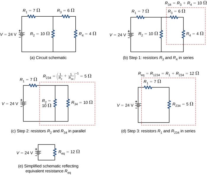
Calculating Resistance in Mixed Circuits
Mixed circuits, a combination of series and parallel connections, present a more complex scenario than purely series or parallel circuits. Understanding how to analyze these configurations is crucial for tackling real-world electrical systems, from simple household wiring to intricate electronic components. This section details the strategies for simplifying mixed circuits and calculating their equivalent resistance.
Understanding Mixed Circuits
Mixed circuits, also known as combination circuits, involve a combination of series and parallel resistor arrangements within the same circuit. Identifying the series and parallel components is the first step in simplifying the circuit. The method to determine the equivalent resistance involves systematically simplifying the series and parallel portions until a single equivalent resistance remains.
Simplifying Mixed Circuits
A systematic approach is vital for simplifying mixed circuits. The simplification process follows a clear procedure. First, identify sections of the circuit that are purely in series or parallel. Second, calculate the equivalent resistance for those individual series or parallel sections. Finally, substitute the equivalent resistance values back into the original circuit diagram, creating a progressively simpler circuit.
This process is repeated until a single equivalent resistance value is obtained.
Methods for Finding Equivalent Resistance
The key to finding the equivalent resistance in a mixed circuit lies in applying the rules for series and parallel combinations repeatedly. The resistance in series adds up directly. For parallel resistors, the reciprocal of the total resistance is the sum of the reciprocals of the individual resistances.
Equivalent Resistance (Series): Req = R 1 + R 2 + R 3 …Equivalent Resistance (Parallel): 1/R eq = 1/R 1 + 1/R 2 + 1/R 3 …
Example of Mixed Circuit Calculation
Consider a mixed circuit with three resistors: R 1 = 2Ω, R 2 = 4Ω, and R 3 = 6Ω. R 1 and R 2 are in series, and this combination is in parallel with R 3.
  R1---R 2
   |     |
   +-----+
   |     |
   R 3
First, calculate the equivalent resistance of R 1 and R 2 in series: R 12 = R 1 + R 2 = 2Ω + 4Ω = 6Ω. Then, calculate the equivalent resistance of R 12 and R 3 in parallel: 1/R eq = 1/R 12 + 1/R 3 = 1/6Ω + 1/6Ω = 1/3Ω.
Therefore, R eq = 3Ω.
Various Mixed Circuit Examples
| Circuit Configuration | Resistor Values | Equivalent Resistance |
|---|---|---|
| R1 (2Ω) in series with (R2 (4Ω) and R3 (6Ω) in parallel) | R1 = 2Ω, R2 = 4Ω, R3 = 6Ω | 3Ω |
| R1 (3Ω) in parallel with (R2 (6Ω) and R3 (9Ω) in series) | R1 = 3Ω, R2 = 6Ω, R3 = 9Ω | 2Ω |
These examples demonstrate the application of the series and parallel rules to determine the equivalent resistance of various mixed circuit configurations.
Practical Applications and Considerations

Resistance calculations are fundamental to understanding and designing electrical circuits. Accurate calculations are critical for ensuring safe operation, efficient energy use, and reliable performance. From simple household appliances to complex industrial systems, the principles of resistance play a vital role in determining circuit behavior. This section explores the practical applications, safety considerations, and factors influencing resistance values in real-world scenarios.
Real-World Applications of Resistance Calculations
Resistance calculations are indispensable in a multitude of applications. In lighting circuits, proper resistance calculation ensures the correct amount of current flows through the bulbs, preventing overheating and potential damage. In electronic devices, accurate resistance values are essential for setting the operating conditions of components like transistors and diodes. Calculating resistance is also crucial in designing and maintaining power grids, where precise resistance values allow for the safe and efficient transmission of electricity.
Circuit protection devices like fuses and circuit breakers depend on resistance calculations to function correctly.
Importance of Accurate Resistance Calculations in Circuit Design
Accurate resistance calculations are vital for the successful design of electrical circuits. Inaccurate calculations can lead to circuit malfunction, overheating, and even fire hazards. Consider a scenario where a circuit is designed with insufficient resistance. The excessive current flow can cause components to overheat, leading to potential damage or failure. Conversely, circuits with excessive resistance can result in insufficient current flow, causing devices to operate inefficiently or not at all.
Safety Considerations in Electrical Circuits
Safety is paramount in electrical circuit design. Understanding the potential hazards associated with electricity is crucial. Overcurrent situations can lead to overheating and fires. Using the correct gauge wire for the anticipated current is essential. Moreover, appropriate insulation and protective measures are critical in preventing electrical shocks.
Proper grounding practices are essential to dissipate any stray current safely to the earth.
Effect of Temperature Changes on Resistance
Temperature significantly impacts the resistance of conductors. Most materials exhibit an increase in resistance with rising temperatures. This phenomenon is due to the increased vibrations of atoms within the material, which impede the flow of electrons. This effect must be considered in circuit design, especially in high-power applications. Materials with a lower temperature coefficient of resistance are often preferred in applications where temperature fluctuations are expected.
For instance, in high-temperature environments, using materials with a low temperature coefficient is essential to ensure stable circuit operation.
Calculating Resistance Using the Color Code on a Resistor
Resistors are often color-coded to indicate their resistance values. This color code system uses a series of colored bands to represent the resistance value and tolerance. The first two bands represent the significant figures of the resistance value, while the third band indicates the multiplier. The fourth band (if present) represents the tolerance. For example, a resistor with bands of brown, black, red, and gold has a resistance of 10 x 10 2 Ω ± 5%, or 1000 ± 50 Ω.
This system is a standard method for determining resistance values without resorting to direct measurement. A comprehensive understanding of the color code is crucial for accurately identifying resistor values.
Common Circuit Breaker Failures Due to Incorrect Resistance Calculation
Circuit breaker failures can stem from several issues, including incorrect resistance calculations. One common failure mode is a circuit breaker that trips too frequently, indicating an overload or a short circuit. An undersized circuit breaker, often due to incorrect resistance calculations, will fail to protect the circuit adequately. Another example is a circuit breaker that fails to trip when it should, resulting in excessive current flow and potential damage to the circuit.
Understanding the correct sizing of circuit breakers based on calculated resistance values is critical for circuit safety.
Complex Circuit Analysis
Delving into circuits with multiple interconnected loops demands a more sophisticated approach than analyzing simple series or parallel configurations. Understanding these intricate networks requires techniques that account for the interplay of currents and voltages throughout the circuit. This section explores Kirchhoff’s laws, circuit simulation tools, and diverse analysis methods, providing a comprehensive understanding of complex circuit behavior.
Analyzing complex circuits necessitates a systematic method to determine the currents and voltages at various points. Traditional methods involving simplifying series and parallel combinations are often insufficient. Instead, powerful tools and fundamental principles are essential.
Kirchhoff’s Laws
Kirchhoff’s laws are fundamental principles governing the behavior of current and voltage in complex circuits. They provide a set of rules that allow us to analyze circuits with multiple loops and branches. These laws are essential for determining unknown currents and voltages within a complex circuit.
- Kirchhoff’s Current Law (KCL): The total current entering a junction (node) equals the total current leaving that junction. This law stems from the principle of conservation of charge. In simpler terms, current entering a node is equal to the current exiting the node. Consider a node where three branches meet; the sum of the currents flowing into the node is precisely equal to the sum of the currents flowing out.
- Kirchhoff’s Voltage Law (KVL): The sum of the voltage drops around any closed loop in a circuit is equal to zero. This law arises from the principle of conservation of energy. It states that the total voltage rise in a loop must equal the total voltage drop. For instance, if you traverse a loop in a circuit and encounter voltage rises and drops, the algebraic sum of these voltages must add up to zero.
Applying Kirchhoff’s Laws
Applying Kirchhoff’s laws involves systematically assigning variables to unknown currents and voltages, then writing equations based on KCL and KVL for each loop and junction. This process leads to a system of simultaneous equations that can be solved using various methods like substitution or matrix methods.
- Example: Consider a circuit with three loops and several branches. Applying KCL at each node yields equations relating the currents at that node. Applying KVL to each loop generates more equations. Solving this system of simultaneous equations using mathematical techniques (e.g., matrix methods) determines the unknown currents and voltages throughout the circuit.
Circuit Simulation Tools
Circuit simulation software provides a powerful tool for analyzing complex circuits. These tools allow users to model circuits, run simulations, and visualize results, without the need for physical prototypes. This greatly reduces the time and resources required for analysis. They are particularly useful for circuits with many components, where manual calculations can become cumbersome and error-prone.
- Software Examples: Tools like LTSpice, Multisim, and PSpice offer intuitive interfaces for creating circuit diagrams, entering component values, and running simulations. These tools provide graphs and numerical outputs, enabling a comprehensive understanding of circuit behavior.
Complex Circuit Diagram
The following diagram illustrates a complex circuit with multiple loops and branches. The diagram displays a combination of resistors, voltage sources, and current sources interconnected to create a more intricate circuit.
“`html

“`
(Note: A placeholder image is shown. A real diagram would replace this placeholder and clearly label components and nodes.)
Description: The circuit in the diagram comprises three interconnected loops. Resistors of varying values are placed strategically within the loops. Voltage sources are connected across certain branches. The diagram’s purpose is to illustrate a complex circuit suitable for analysis using Kirchhoff’s laws.
Comparison of Analysis Methods
Different methods for analyzing complex circuits exist, each with its advantages and disadvantages.
| Method | Advantages | Disadvantages |
|---|---|---|
| Kirchhoff’s Laws | Fundamental, applicable to various circuit types | Can lead to complex systems of equations |
| Circuit Simulation | Visual representation, quick analysis, suitable for intricate circuits | Relies on software, requires some learning curve |
Wrap-Up: Calculate Total Resistance In Circuits
From basic definitions to complex circuit analysis, this guide has provided a comprehensive understanding of calculating total resistance. Mastering these concepts is vital for anyone working with electrical circuits, from hobbyists to professionals. Armed with this knowledge, you can confidently tackle various circuit configurations and appreciate the practical significance of accurate resistance calculations.